Ford Mustang Forums banner

Are all ford pedestal roller rocker arms made incorrectly?

11K views 10 replies 5 participants last post by  petmotel  
#1 ·
Been messing with engines for a long time, but never
delved into aftermarket heads (and adjustable
valve-train geometry) until recently.

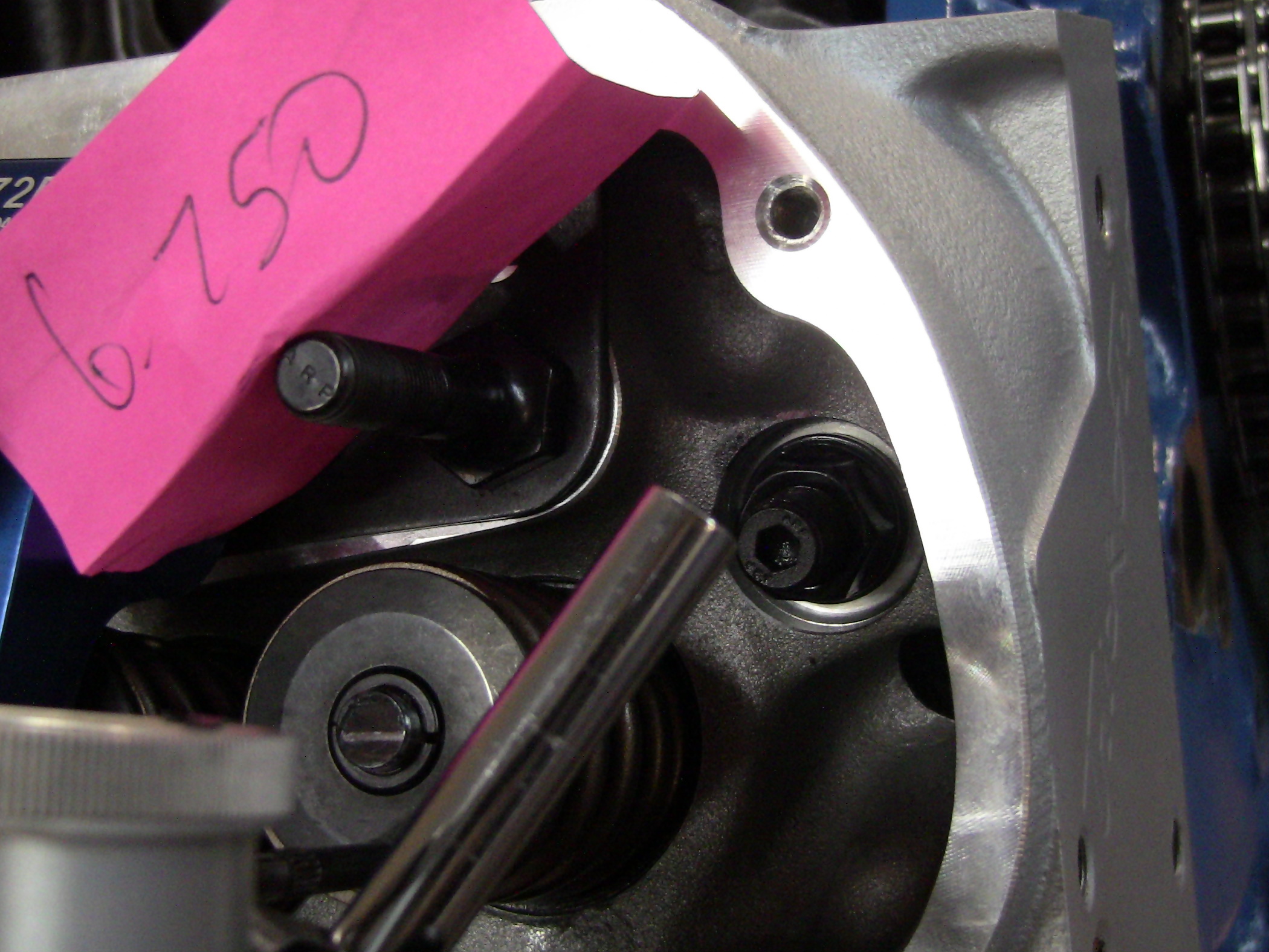
Just set up a set of TW170's on an 86 5.0
(that I bought new, first time heads ever off it)
and came up with what I thought was a pretty
good pattern, .043 width, slightly offset exh side

Image


Previously, I had got a set of GT40X heads a while ago for a mild build
for my dad's hot rod (mostly a show car) that
uses a mildy built AOD and never sees much over 5300RPM.

Ordered a set of 1.6 RR and went about checking
pattern for PS length. Could not get anything
I considered acceptable. All testing was done
with TF's adjustable pushrod and a stock lifter set solid.

I ordered a different set of 1.6's and tried some
no name brand, 1.7's I had lying around. These
are the best patterns I could get. They are
all WAY off center to exh side.

Image

Image

Image


Just bolting all 3 sets of these down with no spacers, yielded patterns of .132, .108, .132,


Image

Image

Image


I figure this is what the average guy who has
a hard enough time even checking for lifter pre-load
is going to get for pattern, as I assume most don't
even know or care what the pattern width is.

Talked to Harland Sharp and they said their pedestal
1.6's have the same basic geometry that everyone else
has, but had chevy and dodge pedestal's that had
shorter fulcrum to roller distances.

After messing around for quite a while with those,
ended up with a best of .071 width, .013 offset to exh side,
using the dodge 5.2/5.9 HS 70036A 1.6 rocker.

Image


I did have to use a total standoff of close to an inch,
vs the average pedestal standoff height of around 6 tenths.

I'm a bit concerned with the height I needed for
the HS rockers, as I don't know if that will affect
rocker side load and/or how square the roller is to tip
@ "higher" RPM (and the fact I will have to get really tall
valve covers, space up the intake, and maybe not fit under the hood).

So I guess my question is, for mild cammed, low RPM
street motor does it even matter? Have to be thousands out
there that bolt these rockers on and go only worrying about
lifter pre-load (let alone the millions of motors that go 150K
with stock stamped rockers and I'm told that "pattern" practically
covers the entire valve tip??).
 
#3 ·
I guess that is my question, what is right?
If right seems to be the slimmest pattern, as close
to center as possible, why wouldn't the manufacturers
make a supposedly ford specific rocker that way?

Or if they were that lazy, start selling the dodge rockers
for fords. It appears that ford specific pedestals are not even close,
no matter what you do to them. I guess if getting the
right rocker means they don't fit under 90% of stock type
ford valve covers, they won't sell any of them?

And yes, I have mic'd lift through most of my efforts
and overall lift did not always correspond with the
thinnest pattern. I suspect it is my method of checking
lift that is the problem, as getting rockers on and off
and re-magicmarkering means sometimes moving the setup
that is doing the measuring. Even at it's best, sometime
it just slips off valve spring retainer and then is a couple
thou off @ rest vs what it just was 2 seconds before that.

Overall I've gotten .467-.474 lift range on a .477/.477 cam
(except for the one set of 1.7's and I didn't bother
measuring lift on those).
 
#5 ·
The proper design of a rocker for a Ford 20* head would have a 160* angle from the centerline of the rocker center pivot bearing to the center of the roller tip at one end, and the bearing center to the center of a 5/16 ball end at the pushrod side. Any angle other than this means that you cannot have a true half lift geometry on both ends of the rocker at the same time. This introduces errors into the valve timing events relative to what was intended by the cam designer.

To further complicate the matter, a rocker designed for valve angles other than 20 degrees will have a different angle designed into them if they are to provide correct geometry to a revised head. For example, an 11* head would need a rocker with 169* between centerlines of the two ends (180* - 11* = 169*)

This is truly not that complex of an idea, and yet few seem to understand it. When the rocker design, and valve train set-up is done correctly, the rocker should be perpendicular to the valve on one end, and the pushrod on the other at exactly half lobe lift (and therefore half valve lift). If either of these conditions is not met, geometry is not correct, and valve train efficiency, as well as timing events will suffer.

The valve train is most efficient (cam lobe translated into valve motion) when the rocker is perpendicular to the valve and pushrod. When installed where this happens at half lift is the most accurate, and most efficient. Any other implementation is a compromise.

The moment you try and determine pushrod length by the tip pattern on the valve stem, means that first you do not understand correct rocker geometry, and second, it's not likely you will determine the length of the pushrods that will provide correct half lift geometry.

The thing about pedestal rockers is that they are not easy to adjust their heights to provide correct geometry. This doesn't mean they're not designed correctly, it just takes more time and persistence to set them up correctly. Certainly not the best choice for a performance application, due to the lack of easy adjustability.

Jay
 
#6 ·
My experience with gt40x heads are that the recommended valves are way too long. Well that was with using a ford specific stud mount rocker not the bolt down. Total MESS.

I'll just put it like this... Performing a "standard" stud conversion on these heads and using the recommended valves I would have be left with an unusable set of heads. I ended up with much shorter chevy valves and offsetting the 7/16 hole for the stud as far to the intake side as the original 5/16 hole would allow. Looking back changing the angle of the stud might have worked better..

I also completely agree with petmotel... I don't look at it as pushrod length. I look at it as rocker position. One can determine the best rocker position to the valve without even installing the heads on a motor. Or in may case before the stud conversion was performed. I'll leave the pushrod side of things to the side for now.
 
#8 ·
If I were going to try and get a good installation in your particular situation, I would first check and see which of the rockers meet the criterion needed. One could make a simple cardboard 160* template to check the rocker angle. If the rocker is indeed at a 160* angle, You can simply set up the valve side, and the pushrod side will be where it needs to be when you get the valve side right.

If the angle is right, and the center to center is within reason on the valve stem when it's perpendicular to the valve (should be past center of valve, but not into about the outer third of the stem diameter), the only thing left to determine is the rocker height. Hopefully at this point, rocker will be too low when the pedestal is all the way down. Then you can simply shim the rocker stands up until you get a half lift geometry. If rocker is too high, the pedestal bases would need to be milled down.

Easiest way to determine the needed rocker height is to measure how much space is under the pedestal stand when the rocker is parallel with the spring retainer when the valve is closed. Figure out what the difference is between that measurement and half valve lift, and shim as needed (assuming the space is greater than half lift).

I hope this makes sense, it would probably be easier to show than explain LOL.

Jay
 
#11 ·
I thought I might try and explain the "merit" or the "why" a half lift geometry is more efficient. If you visualize what happens when the rocker is perpendicular to the valve, and the pushrod, I think it's logical to see that all the cam lobe information is transferred exactly as per the rocker ratio to the valve at this point in the rocker's arc.

Now try and visualize what would happen if the rocker were parallel to the valve, and pushrod (of course realizing this is a hypothetical situation that is physically impossible). No cam lobe information would be transferred to the valve, rocker movement would be at 90 degrees to valve, and pushrod motion.

What can be deduced from all of this is that as the rocker arc moves away from perpendicular to the valve and pushrod linear motions, the less the cam lobe information is imparted to the valve. Once the rocker arc moves past perpendicular, some of it's motion is spent sweeping across the valve stem, and moving the pushrod sideways rather than purely in the linear motion that the lifter and valve move.

Half lift geometry minimizes this inefficiency, and maximizes valve open "area under the curve", as well as minimizing stress on the valve train components. It is due to the fact that it keeps the arc of the rocker closest to perpendicular to the valve and pushrod throughout the cycle. These effects are equally in play whether from the pushrod, or the valve end of the rocker.

Edit: To the OP, I think it's sad and ridiculous that Ford would offer a so called high performance head with rockers that are not designed as a good match. They have certainly been building pushrod engines long enough to have the basics down long, long ago. Pathetic actually IMHO, from a company with the expertise to design and build something as complex as the Coyote engine.

Jay