Ford Mustang Forums banner

The Pizano Method - SBF.Roots.FoxBody

146K views 415 replies 105 participants last post by  vroomzoomboom  
#1 ·
Hello, GP here..

Well I don't usually care to start showing off something that I don't already have sorted, I started to think.. What if something unexpected happened.. like a slip and fall, or hit by a bus, or a carting off to who knows where courtesy of 'them'!? So with that in mind I've decided to officially introduce myself and my SBF Roots FoxBody project in the 'MockUp/Proto-Typing' phase.

I've been at this build for over 3yrs..I wish I could say in that time I've have all the 'tools' I need to attack this project with full Pizano gust-O.. however this is not the case. In any event I'm fully commited to this build and will be happy to post my progress, answer questions, share thoughts/info/ideas and hopefully become a welcomed member of the online community.. (lol, I just read that back.. damn I need to get out more!)

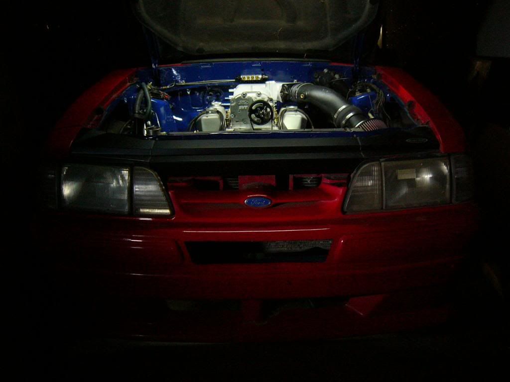
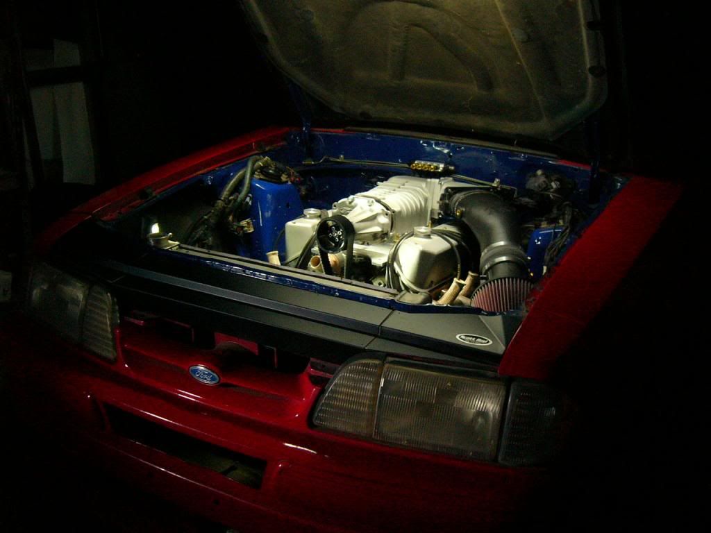
DISCLAIMER: My camera is shxt, My wallet is even shxtier, This is a MockUp of where I'm at/what I have so far, most all of it is just sitting in place or hang'n by a few bolts at the moment..

I'll have to enter some more engine details later..but here's some pics for now and a few quick answers:

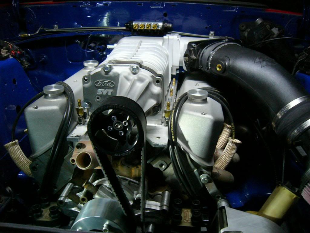
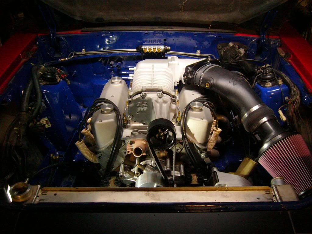
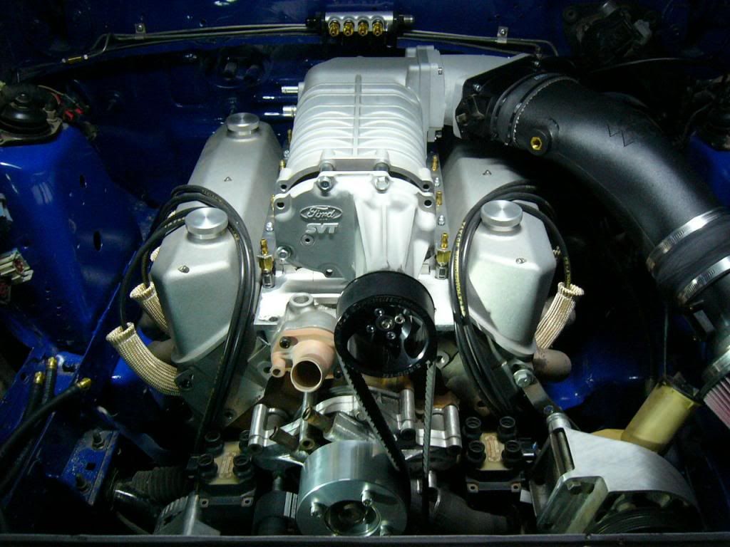
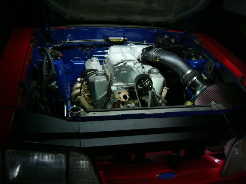
Yes, the lower manifold dose/will accept an Lc-intercooler..Yes, I can close my Stock hood (hell, I can even keep my hood-liner!) Yep, off the shelf Energy Suspension motor mounts.. Yes, if I get a rear set k-member (such as MM's) that moves the eng back, she will clear.. Dedicated 10rib belt runs blower/wp only.. No, stock 5.0 front dress will not work, must use explorer timing cover/pump or remote pump w/alky style cover.. Dizzy is out period, edis/cop/etc only.. Blower (M122 GT500) guts are currently not installed in these pics because I need to finish machining case.. Using an L&M 72mm tb that I'll convert to manual cable.. Fatty plenum is a VMP unit.. Yes, that rad is Huge.. Stock fuel rails - ah No.. Whipple pulley shown in these pics but I've got one of VMP's 6bolt setup's coming in the mail, time will tell which I like best.. Lower pulley options 6"-6.3"-6.7"-7", Upper Pulley 2.4" up to 4".. Ok, I'll say it...TVS!

Thanks for taking the time to check this out, hope you enjoy, any and all input welcome..
GP


Image


Image


Image


Image


Image


Image
 
#6 ·
Sweet project....can only imagine what it took to make the lower intake and fuel ports....if it all works and runs any future in producing the lower manifolds
 
#8 ·
Hmmm, now that I've gotten rid of my distributor and gone to EDIS...
 
#11 ·
Any closeups of the injectors and fuel rails? What are you using for those? That's always been the main problem (other than the distributor), not enough room between the rails for the blower.

Looking forward to progress on this too.


cheers
Ed
 
#12 ·
Looks great
 
#13 · (Edited)
The "rails" in the photos look like brass barbed pipe ends(with the threads bored out) that stick up through a hold-down strap. Look closely.

I've done something similar for the purposes of testing individual injectors on a bench.
 
#14 ·
Hey guys just got logged back in... Firstly thanks for all your kind words, obviously that feels good! Yes things are tight in there to say the least, we're talking every thou counts BiG Time. Lower manifold deffinitely requires crusial attention but the only way to make this fit is with major mods to the blower case itself. Once you've got that fuel rails are a breeze and yes, GT Madness is correct, what's seen there are pushlock fitting bored out and strapped down. I'm still waiting for some 45 degree fittings to come in, then I can run my fuel lines.. wanted that old school alky look with individual feeds.

Gotta take the dog for a walk here but I'll be back,
GP
 
#15 ·
Like I mentioned my camera sucks, I have to take about 5 pictures just to get 1 that's in focus. Got another cam and it did the same F'n thing..it got spiked ;) What this means is that I don't take the amount pics I should and clearly now that I've started this thread..is just unacceptable. So I'll have to get another cam but for now I'll just post what I do have.

So a lot of what I've done could certainly be done by other means, choices I've made have be so based on either means,style or function (usally all 3). After carefully study of where to start with the lower intake a ProComp knockoff of the RPM air gap was chosen, similar to the one you see pictured below..

Image


Image


There are some very important features in this intake that I could not find in any other. For starters the knockoff guys are not stingy with their castings, lots of extra thickness in key places. Also the 'air gap' portion of the bottom intake is nice and low, this give much needed room for intercooler capacity/air flow. The rear water crossover feature is also very important, it is not used but it will become the back 'wall'. The intake bolts seating area is also key as these are left flush and perfect to start building up the top face plate surface. As an added bonus this intake is about as cheep as it gets which is important because it means you're starting with 'clean' material that will weld without complaining! Used intakes can be had cheep for sure but dealing with an oil/fuel/coolant/etc soaked hunk of aluminum can induce a good sized temper tantrum.

So, after the snow storm of aluminum settled, I ended up with a base to start building up material on with the tig welder. Couple of notes, you can buy cutting and grinding disk specific for aluminum and man do they slice like lazer beams compared to your basic metal cutting wheels. Anyhow I didn't take many pics but here's some work in progress shots. Between cutting and welding, I really can't describe how much time is put in to get to a working piece other than to say... don't make any plans for awhile.

Image


Image


I better submit this post before I hit the wrong key and loose it..
GP
 
#165 ·
Like I mentioned my camera sucks, I have to take about 5 pictures just to get 1 that's in focus. Got another cam and it did the same F'n thing..it got spiked ;) What this means is that I don't take the amount pics I should and clearly now that I've started this thread..is just unacceptable. So I'll have to get another cam but for now I'll just post what I do have.

So a lot of what I've done could certainly be done by other means, choices I've made have be so based on either means,style or function (usally all 3). After carefully study of where to start with the lower intake a ProComp knockoff of the RPM air gap was chosen, similar to the one you see pictured below..

Image


Image


There are some very important features in this intake that I could not find in any other. For starters the knockoff guys are not stingy with their castings, lots of extra thickness in key places. Also the 'air gap' portion of the bottom intake is nice and low, this give much needed room for intercooler capacity/air flow. The rear water crossover feature is also very important, it is not used but it will become the back 'wall'. The intake bolts seating area is also key as these are left flush and perfect to start building up the top face plate surface. As an added bonus this intake is about as cheep as it gets which is important because it means you're starting with 'clean' material that will weld without complaining! Used intakes can be had cheep for sure but dealing with an oil/fuel/coolant/etc soaked hunk of aluminum can induce a good sized temper tantrum.

So, after the snow storm of aluminum settled, I ended up with a base to start building up material on with the tig welder. Couple of notes, you can buy cutting and grinding disk specific for aluminum and man do they slice like lazer beams compared to your basic metal cutting wheels. Anyhow I didn't take many pics but here's some work in progress shots. Between cutting and welding, I really can't describe how much time is put in to get to a working piece other than to say... don't make any plans for awhile.

Image


Image


I better submit this post before I hit the wrong key and loose it..
GP
Pretty smart using cuttoff wheel, I would have put it on my cnc vertical and with 4.0 facemilled that thing to death,lol
 
#18 ·
On a Side Note: If any of you out there happen to be running the ProComp intake as it is intended (carb) you might be interested in seeing her guts. Below is the main hulk I chopped out, quit a dramatic imballance between port size and shapes. I have no idea if the 'real' air gap is similar but surely room for improvenets to be had here.

Image


Image
 
#19 ·
Couple more in progress shots of the intake.. Here you can now see how the outter perimeter forms the gasket surface for the top plate. Top plate itself is a cast piece, cast over a forged base plate is important for me in that it will not move,shift or deflect when it is machined. (being that most all of my work for this first proto-type is being done by hand.) The plate comes 'true' with a near perfect mirror finish on both sides under the protective white film you're seeing. This protective film is a nice bonus and works like an erasable marker board for drawing out the floor plan. Props to Jemes Hell at Cobra Engineering for turning me on to this material.

Image


Image


In the second shot you can see how the rear water cross-over help form the rear wall and then the excess remains of the cross-over are removed and the water ports filled in. The cancer bump hanging off the back wall is for a stud mounting or dowel boss that may or may not be used..if not we'll cutter out. You can also see the injectors and modified brass fittings, some may not be familiar with these injectors.. They are Magneti Marelli Weber units more commonly found in the motorcycle world. I pulled them from my Blown sportbike stuff.. specs are 46.8lb@43.5psi up to 60lb@72psi. Their short stature keeps things tidy and I like their metalic body looks, one could use any typical injector but short and slim makes things easiest.
 
#21 ·
If you look at the right side (facing you) of the blower in the first pic, you will see the factory mounting legs of the stock blower case. Not a snowballs chance in hell of dropping on a stock case M122 onto a sbf in a 'low-rider' fashion. Not only do the legs hang over the valve covers but in an direct port efi application many of the legs interfere with injector placement.

Image


sorry for the dark pic..
Image


Now a little chop-chop and presto, just enough room to shine!

Image


Image
 
#23 ·
While I took absolutely no pics of the case mod work at the time, I'll grab some pics next time she's on the bench. Untill then, below is a stock M122 case, mine now mounts from below such as these two examples in the second pic (similar to many other cases like Magnuson,Whipple,Etc) Pretty basic really just move in the holes and tap, there is lots of meat. Lol.. I was a total basket case of nerves..do not slip-do not drill too far-is this shxt straight-do not pile up that tap fxcker! But it turned out even better than expected and this was a good feeling...yes.

Image


Image
 
#25 ·
Dude - you absolutely win the prize for "coolest looking PD blower install on a SBF." Definitely cooler looking than mine. And I like the compactness. The injectors are pretty trick. In fact, the whole thing has a really cool vintage/modern look to it. I have one question - what's up with the valve covers? They look cool, but centerbolt? Explain, please.