Ford Mustang Forums banner

Powerdyne BD-11a versus Powerdyne XB-1A dyno numbers - need some input

8K views 54 replies 6 participants last post by  Big White Ford Explorer  
#1 · (Edited)
Powerdyne BD-11a versus initial tuning Powerdyne XB-1A dyno numbers - need some input

I came here to this forum as it seems this is the place where there is the most people that have experience (from back in the day) with the Powerdyne Blowers.

To start off, here is a bit of relevant info regarding my setup

Current Mods on my 2000 Ford Explorer Limited with a 5.0L 302 Windsor: (Keep in mind, I am AWD and using a 4R70W so number compared to the 5.0L Mustang will be lower. The stock 5.0 2nd gen Explorer dynos at about 160 rwhp)

Powerdyne XB-1a Gear Drive Supercharger (Si Trim) with 2.7” Supercharger Pulley and 6.5” Crank Pulley (2023 Production Model)

Custom Water to Air Intercooler

90mm SCT MAF

SR Performance 75mm Throttle Body

Custom 80mm Intake Elbow

1” TrickFlow Intake Spacer

Custom Oil Catch Can

Ford Mustang Cobra IAT Sensor

Ford Mustang GT500 EV6 Fuel Injectors

Walbro 255 lph in tank fuel pump

1997 Ford Explorer Tremor Concept Truck Style aluminum air box

OBX Headers

2.5” Stainless mid X-Pipe between headers and mufflers.

Flex-A-Lite e-fan

Custom built 4R70w transmission connected to a Borg Warner AWD Transfer Case


3.73 rear end

(2) Saleen Borla Stainless Exhaust Systems (true duals configuration) - Saleen XP8 98-0034 and Saleen XP8 00-0023

I've attached three dyno sheets from my experience (so far) with the Powerdyne BD-11a Supercharger and the Powerdyne XB-1A supercharger. Obviously, the dyno results from the XB-1A are just preliminary dyno tuning numbers and I honestly feel there is a considerable amount to pull out of this setup. Hoping the community here can take a look at these past results and give some input
  • RWHP 303.07 - Torque 336.51
  • This was the last dyno of the BD-11A before the rebuild by Jon Bond Performance and original bearing failure.
  • I was running the following pulley combo for this pull
  • 2.7 (2.65) SC Pulley and 6.5 (6.485) crank pulley
  • Stock Impeller, stock belt and stock bearings
  • Pull cutoff RPM was ~ 5000 rpm
  • Max blower rpm 36,712 - 37,319
  • Boost level observed with this pull was right at 6lbs

  • RWHP 287.50 - Torque 337.08
  • This was the 1st dyno after the rebuild of the BD-11a by Jon Bond Performance
  • The following work was done by Jon Bond
  • New bearings Billet Impeller New internal belt
  • I was running the following pulley combo for this pull
  • 2.8 (2.86) SC Pulley and 6.5 (6.485) crank pulley
  • Pull cutoff RPM was ~ 4800 rpm
  • Max blower RPM 33,195 - 33,985
  • Boost level observed during this pull was in the high 5lb range.
These are the next dyno runs with the new Powerdyne XB-1a and 16 fin MID billet impeller (Si Trim)
  • RWHP 268.06 - Torque 304.89
  • Pull cutoff RPM was 4800 rpm
  • I was running the following pulley combo for this pull
  • 3.1 SC Pulley and 6.5 (6.485) crank pulley
  • Max blower RPM 34642 - 34722
  • The approximate boost level observed during this pull was in the 4lb range

  • The next 3 runs were with the below SC and crank pulley combos

  • RWHP 295.31 - Torque 325.30
    • Pull cutoff RPM was ~ 5600 rpm
  • RWHP 296.17 - Torque 326.34
    • Pull cutoff RPM was ~ 5600 rpm
  • RWHP 297.52 - Torque 329.53
    • Pull cutoff RPM was ~ 5600 rpm
    • The pulley combo I was running for these (3) pulls was
      • 2.7 (2.65) SC Pulley and 6.5 (6.485) crank pulley
      • Max blower RPM 46511 - 47279
      • The approximate boost level observed during the last 3 pulls was in the 6psi to just at 7psi range
So initially I mentioned that we thought there was a boost leak in the WTA intercooler. The WTA intercooler system was leak checked (up to 20 PSI - maybe 5 to 10 minutes?) and no leaks were found. It was determined that the cap on the intercooler system reservoir cap was letting expanding intercooler coolant escape through the pressure hole. Remember, the intercooler cooling system is a closed system. No leaks were found in that system. Installer thinks the system was filled too high and is going to come up with a revised system for the reservoir.

A smoke test was also performed and nothing was noted. We are still investigating what other issues there possible could be.

Obviously, I think we all expected to see a bigger/better result from the XB-1a. At the moment, they do not feel there is a boost leak. They think "maybe" this could be related to belt-slip with the 2.7 pulley and we are further investigating this. Belt tension is going to be checked and additional pulls with the 2.7 and 2.8 pulleys will be made with a full boost level recording (since the dyno boost gauge during the tuning pulls wasn't functioning consistently ) and see where we are at that point.

Thinking based off of the past dyno results of the BD-11a both in stock form and after JB’d initial rebuild - I should be able to achieve 8lbs or more of boost and 350+ RWHP on my setup with the XB-1a.

Some additional info to answer the questions and comments by Jon Bond

The company who bought the Powerdyne rights from 02 Force is now making new Powerdyne XB-1a Superchargers Here is a quote from them - "What had happened was".... the company that bought out Powerdyne was looking for a another company to start re-making the XB again, for them, before they also ultimately threw in the towel as well, and sold out to us...(they just bought the company as an investment, they got in over their heads, they were not very knowledgeable 'car guys' )

They came to us with a proposal, and to TorqStorm - but since we ended up buying them out, TorqStorm couldn't make the XB, as it was, without patent infringement, so they came up with their own version,looselt based on the XB, with different internal sizes, bolt patterns, etc, etc....so it looks similar to a BD / XB, but everything is altered just enough...
Anyway, They made their modified version of it with a much smaller impeller, so they could spin it faster, like a turbo, but it also does not perform well - b/c you cannot spin a turbo sized impeller fast enough , WITH GEARS, to make it reliable. They mainly market it to old school hot rods with old, large motors, but it only makes 5 or 6 pis at best, as well, like the BD. "

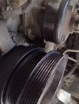
Here is the XB-1a that they built for me -

They offer different impellers and trim levels on the new production XB-1A blowers - Quote from them -

"As I stated before the impellers are just like Vortech trims / external sizes, so do your research on the different trim levels Vortech offers, and these are the same albeit slightly different aftermarket designs, but same external dimensions, and you could expect very similar performance.
7/7 fins - best flow at higher rpm, loss at lower rpm
8/8 fins - best flow at mid rpm, closest like stock
16 tall fins - best flow at low to mid range, loss at high rpm "

Here is another guy with an XB-1A that upgraded to a YSi trim level on that blower during a self rebuild?. In the video he says that they make Vortech Parts to fit on the XB-1A. I do not know as much as you do, but you might be able to understand better from the video. He seems to have the and upgraded impeller. He does a comparison between the factory and replacement impeller

Also, more from their build spec sheet regarding Impeller Trim - Quote "A (STOCK) (3.00 ID) - Si Trim (3.08 ID) - T Trim (3.25 ID) - Ti Trim (3.50 ID) - YSi Trim (3.70 ID)

Here is a video of three of the last dyno runs -

Here is a video of the XB-1A just after installation and final fitting -

and just after I received the XB-1A -


Image

Image

Image
 
#2 ·
Couple of questions
During these different sessions, what were the condition differences. Temp Humidity, Etc.
On each day / session what were the blower discharge temps and manifold inlet temps?
Are you running 6 rib or 8 rib blower pulleys?
I noticed on the dyno video, you have only the rear wheels on rollers.
You mentioned all wheel drive early on. Is the vehicle now front wheel drive only
If so are all the all wheel drive components removed?
You mention rebuilt trans, what converter is installed?
Can you provide detailed pictures of the blower and intercooler piping, it looks like piping sizes change numerous times.
 
#3 ·
Couple of questions
During these different sessions, what were the condition differences. Temp Humidity, Etc.
On each day / session what were the blower discharge temps and manifold inlet temps?
Are you running 6 rib or 8 rib blower pulleys?
I noticed on the dyno video, you have only the rear wheels on rollers.
You mentioned all wheel drive early on. Is the vehicle now front wheel drive only
If so are all the all wheel drive components removed?
You mention rebuilt trans, what converter is installed?
Can you provide detailed pictures of the blower and intercooler piping, it looks like piping sizes change numerous times.
Hi - thanks for the reply
  • At the bottom of the post, I’ve attached some photos during the install fitting
  • You can see after it was running here :
  • Running a 6-rib setup
  • Trans is rebuilt. Running the stock 2nd generation Ford Explorer 4R70w torque converter
  • Truck is AWD (Borg Warner 4404). Front driveshaft was removed for Dyno runs
  • I’ll check for Dyno conditions but I think they were all pretty consistent - high 60’s, low 70’s and low humidity
  • I do not think blower discharge temps were measured but IAT’s never exceed 120 degrees under full boost (measured at the manifold)

  • Image

    Image

    Image

    Image
 
#4 ·
Needs a 7 or 8” crank badly. Then go to a 3.xx blower so you’ll stop getting slip.
 
  • Like
Reactions: CDW6212R
#7 ·
Super tight doesn’t always help. I would also consider making sure the blower pulley is textured.

Do you have any logs of boost pressure?
 
#8 ·
Our next steps include doing multiple boost measurements during runs with both the 2.7 and 2.8 pulleys. We want to measure boost, just after the supercharger, and before the heat exchanger, then after the heat exchanger, and before the throttle body, and then finally in the manifold.

on the last combo, Dyno runs with the XB-1a during tuning, the boost measurement device of the Dyno was not functioning properly, and we were only using a manual gauge to eyeball it. The next runs will have that corrected.

The plan is also to check belt tension with a krikit tension tool

Image
 
#9 ·
Your pulley arrangement certainly is not helping. You can generally see belt slip by taking the DynoJet run file and using their free WinPep reader software and looking at the runfile (if you dont have get it from the dyno owner) and removing all the smoothing when looking at the file. The other, simpler way to see it is to feel / look around the pulleys for black belt dust.

With regard to slippage, you need to consider belt width and wrap area which combines to provide belt contact area. More contact = less slip. To minimize slip, you should be looking a 3.15 to 3.50 blower pulley, which of course will slow down the blower, you then need to compensate by increasing the size of the lower / crank pulley.

There are 2 ratios that determine impeller speed, the internal gear step up ratio, which is fixed and the pulley ratio which you can change. So if you have 6.5 lower and 2.75 upper, you have a 2.36 step up ratio.

If you need a larger blower pulley to reduce slip (say 3.15) and also want to increase blower speed, then you need something like a 8” lower / crank pulley with 3.15“ upper, which would provide a 2.53 step up ratio.

Also moving to an 8 rib setup will really help with belt traction and consider the use of a GripTec blower pulley which will also help with slip.

Some other thoughts.
Typical Chassis dyno losses (Dynojet) for a stick car is in the range of +/- 15%. Having the AOD will increase that to 20% or more. Connecting the transfer case onto the drivetrain will further increase drivetrain loss, even if not connected to the front driveshaft.

Depending on the temp differential between blower discharge and intake (pre and post intercooler) you will probably see some pressure drop across the intercooler.
You mention the intercooler is a custom piece, is it possible that it is restricting airflow?

Looks like you have spent alot of time and money trying to make the Powerdyne provide the performance you want. Maybe you might consider going the tested and true route and get a Vortech blower.
 
#11 ·
Your pulley arrangement certainly is not helping. You can generally see belt slip by taking the DynoJet run file and using their free WinPep reader software and looking at the runfile (if you dont have get it from the dyno owner) and removing all the smoothing when looking at the file. The other, simpler way to see it is to feel / look around the pulleys for black belt dust.

With regard to slippage, you need to consider belt width and wrap area which combines to provide belt contact area. More contact = less slip. To minimize slip, you should be looking a 3.15 to 3.50 blower pulley, which of course will slow down the blower, you then need to compensate by increasing the size of the lower / crank pulley.

There are 2 ratios that determine impeller speed, the internal gear step up ratio, which is fixed and the pulley ratio which you can change. So if you have 6.5 lower and 2.75 upper, you have a 2.36 step up ratio.

If you need a larger blower pulley to reduce slip (say 3.15) and also want to increase blower speed, then you need something like a 8” lower / crank pulley with 3.15“ upper, which would provide a 2.53 step up ratio.

Also moving to an 8 rib setup will really help with belt traction and consider the use of a GripTec blower pulley which will also help with slip.

Some other thoughts.
Typical Chassis dyno losses (Dynojet) for a stick car is in the range of +/- 15%. Having the AOD will increase that to 20% or more. Connecting the transfer case onto the drivetrain will further increase drivetrain loss, even if not connected to the front driveshaft.

Depending on the temp differential between blower discharge and intake (pre and post intercooler) you will probably see some pressure drop across the intercooler.
You mention the intercooler is a custom piece, is it possible that it is restricting airflow?

Looks like you have spent alot of time and money trying to make the Powerdyne provide the performance you want. Maybe you might consider going the tested and true route and get a Vortech blower.
Thanks very much for the additional input!

In my last conversation with the shop, we did talk about a larger crank pulley. Right now it’s not clear exactly how much room I have to go bigger. Did you see the photos above of the crank pulley that is currently on the truck? Just curious of your opinion if it looks as if there is room enough to go larger.

Regarding going to an eight rib - that might possibly be even more of a challenge due to clearance issues both at the supercharger pulley and the crankshaft pulley. Still it might be possible. Right now there is not a lot of space between the crankshaft pulley and the Efan. We finally found an excellent efan solution that works quite well and I would hate to have to try to find another that provided more clearance for an eight rib pulley there. If I remember correctly, the installer said that there “might” be some clearance issues at the supercharger pulley if we went with something wider. I do like the idea of the griptech.

During our next Dyno runs, I’ll check as you described for signs of belt slip.

I know exactly what you mean about the 4R70W and the Borg Warner 4470 all wheel drive. The all-wheel-drive is the same type of system that they used on the GMC Typhoon. We had one guy on the Explorer Forum that it was running over 500 hp constantly through that system and he had no issues from it. I really like it and it fits the vision of my project to keep it even though I know it’s sucking up a lot of power.

The intercooler core of the w2A intercooler system is an off the shelf part - just with a custom implementation. We checked the rating when putting the system together
  • Info on the intercooler core
  • WAT001006
  • This water to air intercooler kit is superior to air to air intercooler solutions.
  • The Intercooler Core
    100% Lightweight aluminum, No Epoxy Used In Core
    Recommended for over 700 CFM
    Pressure Drop: Less than 0.1 PSI. This is not a typo! Liquid/Air Intercoolers have incredibly low pressure drop.
    Air Inlet/Outlet: 3.0"
    Water Inlet/Outlet: 1/2" NPT
    Core Size: 10"x4.5"x4.5" (Endtanks add to length)
    Maximum water pressure: 70 PSI
    This intercooler has the inlet and outlet on the SAME SIDE.
    WARNING!
    Some Water to Air Intercoolers that you can buy online do not contain true water to air cores. A true water to air core has water passages that are much smaller than the air passages. This is part of what allows the water to air intercooler to be so small and have such low pressure drop. Some water to air intercoolers that you buy online use an air to air core design where the air passages for ambient air and intake air are the same size, with an enormous loss of efficiency.
 
#10 ·
BTW in the Torque Storm drawing above, the lower idler shown is actually holding the belt away from the lower pulley and reducing the belt contact area on the lower pulley.
 
#12 · (Edited)
Image

My post cut off before I finished. So during the next Dyno runs, we intend to measure the boost before, and after the intercooler core to see if we’re having significant boost loss either from restriction or something else.

also, thanks for your information about the Torqstorm drawing. I only provided that to the installer to give him some possible ideas on how we could potentially add a second tensioner on the bottom side of the belt. I’ll pass along your input.

When I moved from the BD-11A to the XB-1a definitely considered the potential of using a Vortech.

Vortech was no help. They told me they never made a kit for the 302 Explorer, and they had no information or desire to help me with it. They did say they would build me a V1 head unit though.

My installer seemed to think the V1 would not work so had an XB-1a built since it is a direct swap on to the BD-11a bracket.

Only now did I found a really old obscure post someone made about modifying a Powerdyne or Vortech 94/95 Mustang bracket to allow use of the V1 on the 302 Explorer. Obviously, there was no follow up so I have no idea if it actually is real or it even worked for the original poster.

This is what I found
****

Mounting Bracket 4FG011-021 Modification
Remove ~ 1/8” from the 4 mounting bosses on the rear of the mounting bracket (4FG011-021).


Discharge Tube 4FA012-020 Modification
Loosen Allen head cap screws /clamps where they bolt the volute on the supercharger.
Mount supercharger onto previously installed main bracket and supercharging mounting plate.
Butt the Discharge Tube to the throttle body opening, rotate volute until discharge outlet on the volute lines up with the Discharge Tube inlet.
Over lay the Discharge Tube between the throttle body and the discharge outlet. Mark the Discharge Tube.
Cut the Discharge Tube to the angle previously marked.
Snug down the Allen head cap screws /clamps so the volute cannot move.
Remove the supercharger and tighten the Allen head cap screws /clamps.
Reinstall the supercharger and secure with four (4) 3/8-16 x 1" bolts and AN washers.

Also, here is a drawing of a V1
 
#13 ·
I had both 96 and 98 V8 Explorers and loved those vehicles, especially the full time all wheel drive, great engine drivetrain combo.

I was not implying that you should not use the transfer case, only that during a dyno pull, its presence will further increase driveline loss and lower readings.

Is it possible that the bypass valve is leaking boost back into the blower inlet? I’ve see that before.

From your pic, it looks like a significantly larger blower pulley would run into the water pump pulley. Seems like the PowerDyne kit has the blower pulley set further back toward the engine than Vortech or Procharger. On my 95 Cobra / Vortech setup it was very close, but allowed me to run a blower pulley which overlapped the water pump pulley (had to remove the lower pulley to change the accessory belt!) Doesn’t look like an option here.
 
#14 · (Edited)
during my last conversation with the installer, we did discuss the issue with the clearance and the water pump pulley. There was some mention about finding a solution for doing something with the water pump pulley – perhaps something different there as long as it was providing the same flow as the current water pump. I think we really need to understand just how much space we have to work with under the current set up and determine if it would make sense.

Regarding the BOV - this is something that I was always concerned about going back to the original BD-11a installation. I had bought the last new PowerDyne Ford Motorsport SVO Explorer kit, and it sat on my shelf for I think more than a decade before I actually got around to installing it. With it was a new plastic style Bosche bypass valve. It always lingered in the back of my head that perhaps because of age that thing wasn’t working 100%.

When we installed the XB-1a, I bought a new comparable Bosche bypass valve - Kayser 06A 145 710 P. They don’t make the Bosche any longer so I went with this German one that they use on the turbo SAAB and Audi that specs the same part number as the original Bosche I had. I just hope the internal spring rate is correct for the amount of boost that I’m producing. I can’t imagine that it would be a problem because it’s not like I’m putting out 20 pounds or more.

During our testing of multiple boost point measurements at the next Dyno session, perhaps we should test this as well

Understand what you’re saying about the all-wheel-drive.

From what I’ve been told with the Explorer, 302 paired to the 4R70W and the Borg Warner 4404 AWD system, I should account for at least a 25% loss and maybe more (30%)

Using those figures and applying them to the Dyno numbers of the previous sessions - at the motor I perhaps have:

At the motor:
  • Stock - 215 HP - 280 Torque (Dyno 168.75 - 147.50 HP 210 - 196 Torque)
  • Stock BD-11a 2.7/6.5 pulley: 405 - 434 HP and 449 - 480 Torque (Dyno 303.07 HP - 336.51 Torque) - just over 6 lbs of boost
  • Jon Bond rebuilt BD-11a 2.8/6.5 pulley: 383 - 410 HP and 450 - 482 Torque (Dyno 287.50 HP - 337.08 Torque) - high 5 lbs of boost
So comparing this to the high run of new XB-1a, I am seeing close to the same numbers and I’m using the same pulley and perhaps observing the same boost as the BD-11a. Shouldn’t I see more with everything else being equal or perhaps I’m just not spinning the XB-1a fast enough?

The stock BD-11a supposedly flows 800cfm and the stock XB-1a supposedly flows 1200CFM
  • 2023 XB-1a 2.7/6.5 pulley: 396 - 425 HP and 439 - 471 Torque (Dyno 297.52 HP - 329.53 Torque) 6 to 7lbs of boost
Here I was spinning the blower at 46511 - 47279 rpm at 5600 engine rpm but the max hp of this run came at 5.08k rpm (41594.22 - 42281.22 blower rpm). Horsepower dropped slightly between 5100 and 5600 rpm
 
#15 ·
Looks like the water pump hub is much larger than the one on my 95. Since both are 8.2 / SBF the center of the crank to center of the pump shaft should be the same. As you can see below the hub on my pump is much smaller and the pulley is stepped, allowing a much larger crank pulley (8.25"). If you could achieve the same setup by changing to a different water pump - without altering pump flow or rotation (95 is reverse rotation), then a stepped pulley would solve your problem and allow you to run a much larger lower pulley and a larger upper, achieving both more belt wrap and faster blower crank to blower speed.

BTW, do you know what the internal gear step up ratio is on your current PowerDyne blower? Most Vortech's are 3.45:1 and some 3.60:1. Would need to know yours to calculate impeller speeds.

Image


Image


Image
 
  • Like
Reactions: CDW6212R
#16 ·
Looks like the water pump hub is much larger than the one on my 95. Since both are 8.2 / SBF the center of the crank to center of the pump shaft should be the same. As you can see below the hub on my pump is much smaller and the pulley is stepped, allowing a much larger crank pulley (8.25"). If you could achieve the same setup by changing to a different water pump - without altering pump flow or rotation (95 is reverse rotation), then a stepped pulley would solve your problem and allow you to run a much larger lower pulley and a larger upper, achieving both more belt wrap and faster blower crank to blower speed.

BTW, do you know what the internal gear step up ratio is on your current PowerDyne blower? Most Vortech's are 3.45:1 and some 3.60:1. Would need to know yours to calculate impeller speeds.

View attachment 1103415

View attachment 1103405

View attachment 1103414
That engine is beautiful!!

I agree about the water pump. I’ll speak to the installer about possible options

The internal gear step-up ratio on PowerDyne XB-1a is 3.45 just like the Vortech V1. Jim Wheeler from Vortech is who started Powerdyne. I’ve been told that the XB-1a is the same as the V1 in a Powerdyne case.
 
#17 ·
If this is a stock explorer engine stock intake stock cam stock heads there is no reason to rev it past 5000 rpm. The cam is done between 4800-5000 rpm and valve float after that. There is belt slip happening for sure and I'd send the head unit pulley in to carbonite coatings to be coated instead of trying to add another tensioner pulley. Don't try to over spin a Powerdyne. Stay under the max impeller speed limit. Doesn't matter if its a billet impeller or not. Doesn't matter if its new rebuilt with new bearings don't spin it to max rpm or even close to it.
 
#18 ·
I had a XB1A and changed for a v3 vortech. Pulleys were 8” crank and 2.7 on xb. 8” crank and 3.47 on vortech, both made 14.5 psi of boost on a built 351w, AFR 195 heads, trick flow R 90mm intake and tb, tfs stage 2 cam. Both set ups were 8rib. The XB1A was being severely overspun due to my ignorance and bearings were toasted. I would shoot for 7-8” crank pulley and a much larger sc pulley. 8rib if able and should pull around 10psi and now you need to keep a close watch on fuel pressure and AFR- possibly needing a bigger fuel pump, injectors, lines, regulator, rails..
 
#19 ·
Hi and Thanks for the reply.

with your Powerdyne XB-1a, what rpm were you shifting your vehicle (at what rpm did you hit 14.5 psi?). Do you have any Dyno sheets from when you had that blower installed?

it’s looking like we are going to try to put a bigger, crank pulley, but trying to find a solution for reducing the water pump pulley size on the Explorer. That’s the number one thing that’s keeping me from increasing the crank pulley size.

I already upgraded to GT500 injectors, Walboro 255 l/h fuel pump. Not running the FMU from the BD-11a kit. My understanding is the fuel rail and misc on the Explorer should support where I’m going with this at this point.

Thanks again for the input!
 
#20 ·
I shifted at 6400 rpm. Would make 10-12 psi around 5200rpm. No dyno pulls but had to go to 80lb injectors due to being at calculated 126% duty cycle on 60’s- 90% on the 80’s so over 700 crank.
 
  • Like
Reactions: CDW6212R
#21 ·
So ran the calculator and it seems you were spinning the blower at 65422.22 at your 6400 shift point and at 53155.56 at 5200 when you saw 10-12 psi.

It’s good information and it seems to be consistent with what I’m thinking which is this blower just needs to spin up more to generate the type of boost that I’m looking for. Right now, I’m only spinning it 46/47k max.

How long did your bearings last in your Powerdyne under those conditions? Were they stock bearings or from one of the known rebuilding companies? Were you running the stock impeller or something upgraded?

Thanks again
 
#22 ·
I don’t have the #s with me now but the V3(Si impeller) was spinning around 53k at 6400 if I remember correctly. Just over the max of 52k. Never had an issue. Was definitely too much for the XB1A. I had bought the XB1A with that pulley combo and the bearings didn’t last long. Sent it for a rebuild at superchargerrebuilds and bought the vortech.

My point though is that with the bigger lower, you can turn a bigger upper and will help with belt slip and get you more boost based on your goal/impeller speed, etc..
 
#23 ·
So we came up with this as a small 1st step with the Powerdyne. Hoping this gives a bit more for reducing any possible slippage. Coming off of the lower alternator bracket we put an idler pulley that basically puts pressure on the bottom of the supercharger belt (pushing up) and then tensioned it (the belt) to the appropriate tension measured using the Gates KriKit tool

Image

Image
 
#24 · (Edited)
Image

Ok, I have an update and a couple conclusions. Also curious to hear any addition input/thoughts about it

As I previously posted, we made some effort to address potential belt slip I was experiencing with my 2.7/6.5 pulley combo (The Powerdyne XB-1a has a 3.44 gearbox ratio). It seems that this effort paid off and we saw some big torque increases through the rpm range. FYI, it’s estimated the 2000 Explorer with 302 5.0 Liter Windsor V8 has a driveline loss of 25% or more because of the 4R70W automatic transmission and Borg Warner 4405 AWD system. Add this to these numbers if you want to know the crank hp/torque numbers.

It also appears that the tune needs to be adjusted because it appears to sharply pull engine timing (???) at 4500rpm. My understanding is since we are making more power/boost due to reduced belt slip (??) the previous very safe tune can be adjusted and we will ultimately see these new gains continue up through past 4500 rpm instead of the current drop due to pulled timing. Shop estimates an additional gain of perhaps 25 hp or more after 4500

Here are two Dyno sheets

The 1st shows a comparison between last high Dyno run on October 9 before fixing the belt slip problem (ORANGE) and October 30 (GREEN) after the effort to fix it. You can see the gains in the lower and mid rpm range

There was some question about how much boost is being lost by the WTA intercooler. The second Dyno sheets show the last two runs on October 30. If you see the bottom graph on that sheet, you can see the pre-intercooler boost pressure (GREEN) and post-intercooler (RED).

We are only seeing a peak of 0.11lbs of boost loss due to the intercooler.

So some conclusions and next steps??

* It appears we had some success in reducing belt slip with the 2.7/6.5 pulley combo

* Previous very safe tune needs to be adjusted as it seems to be pulling timing at around 4500 rpm

* Need to find a way to install a bigger crank pulley The current 2.7/6.5 pulley is now only spinning the blower in to 40k rpm range. I’m told this blower is “pesky” and sees bigger gains at higher rpm’s when compared to the BD-11a. Right now the water pump pulley on the Explorer prevents me from installing a bigger supercharger crankshaft pulley (see last photo). I am no longer driving a fan off the water pump since going to an efan solution. The Explorer 302 uses a much shorter front dress(???) that the Mustang 302 so I might need to find a custom solution to solve this issue. A bigger crank pulley will allow me to spin the blower faster with reduced chances of belt slip which should result in even more HP and torque gains on this combo.


Image

Image


Image
 

Attachments

#25 ·
You're brave with that idler. It's probably going to bend/break off.
 
  • Like
Reactions: CDW6212R
#29 ·
Ah memories, XB1A.
6037 heads, stock cam, explorer intake, SBE, I think I did 389 on the dyno. Swap in 331, AFR185s, blower cam, rpm2, did 442@5000rpms (thru the cats and had to cut due to an incompetent tuner).

Anything under a 2.93 pulley is going to slip on the XB, where 8-rib is mandatory. Still had slip on a 8rib 2.7 setup.

Agree w/Nitrous SSC... idler pulley bracket is similar in concept to the SN95 mounting (I still use it on mine!), but a hex standoff/material will flex, adding to slip and possibly brake or belt will slip off. You need the cobra idler pulley which is 10ribs wide & metal (which I use). The SN95 bracket is a thick 3"x1.25" dia. welded hardened steel rod.

ABEC7 bearings in the XB will hold up to 60k rpms. My originals got toasted under a 2.7 pulley.

The biggest problem with the XB is the impeller seal. It's pretty weak (design). Make sure you have a bigger bypass and good way to rid of ring blow by. Otherwise the seal will leak and only way to fix is replace. Weeping oil will mess your tune and you'll lose power.

Most boost I saw was 12psi on a 7"/2.7 on the 302. On the 331, 8psi. IAT were thru the roof (180+). XB is pretty inefficient compared to today's stuff. CFM is nowhere near 1200 as originally stated, more like a weak 950: an intercooler will be a lot of drag for it too (2 steps forward, 1 back) where meth maybe a better option.

Redesigning the front bracket and adding a big Tial bypass I swapped to a Novi1500 reusing everything else. No impeller seal issues, quieter, no belt slip. With a 3.05 pulley seeing 12psi at 5400rpms, IATs under 150, MAF log says I'm pulling ~400kg/hr more there. Haven't taken it to my 6200 redline yet as logs say I maybe running out of fuel. World of a difference in power through out the range. Also run the cobra WP pulley since you probably have the SN95 short accessory mounts.

Yeah, Gates krikit manual says 180ft-lbs+ for new belts, 130 for used belts using their tool. It's good.
 
#31 ·
shop sent over some WP8 files and this expanded Dyno sheet. Will these wp8 files have what is needed to understand what is happening in these runs? Anyone here can read these files?? Here is the Dyno sheet. The Dyno pull times and the bottom can be matched to the previous ones I posted

Also, when asked the shop about IATs during the pulls they commented:

“ Avg. air charge temp was below 120F. After the pulls you could feel the difference between before and after the intercooler.”

Image
 
#32 ·
Is there anyway to jam a baby Vortech in there like the SCi?
 
#34 ·
As others have said, you need to replace that idler you added with something more substantial. it is hung out so far on that flimsy post it WILL BREAK and maybe take other stuff with it when it does. As I said in an earlier post your slippage problem is because of the 2.7" blower pulley, not the 6" crank pulley.

The reason to increase the size of the crank pulley is:
a) When you increase the blower pulley size, it will slow the blower down unless you increase the size of the crank pulley.
b) To increase the overall blower speed beyond where it is now.

The bottom idler shown crossed out in the arrangement shown below us "unwrapping" the belt from the crank pulley. Changing the arrangement to as shown with a SUBSTANTIAL idler will provide the best belt wrap for both crank and blower pullies.

Do not increase just the crank pulley size as it will add to the slippage problem. Look at the math I provided in my earlier post in this thread.

Another thing you should do is adjust the smoothing in the DynoJet WinPep App down to 2 (now set to 5 look in the RH top corner of the graph). By doing this, you will be able to "see" the belt slip on the graph.

Image


Beyond spinning the blower faster and making sure you have a good timing throughout the range, a cam and valve springs are prolly your next step for more power. The explorer cam was designed specifically for torque and to be done at 4500-5000, which is where your combo is maxing out.
 
#35 ·
As others have said, you need to replace that idler you added with something more substantial. it is hung out so far on that flimsy post it WILL BREAK and maybe take other stuff with it when it does. As I said in an earlier post your slippage problem is because of the 2.7" blower pulley, not the 6" crank pulley.

The reason to increase the size of the crank pulley is:
a) When you increase the blower pulley size, it will slow the blower down unless you increase the size of the crank pulley.
b) To increase the overall blower speed beyond where it is now.

The bottom idler shown crossed out in the arrangement shown below us "unwrapping" the belt from the crank pulley. Changing the arrangement to as shown with a SUBSTANTIAL idler will provide the best belt wrap for both crank and blower pullies.

Do not increase just the crank pulley size as it will add to the slippage problem. Look at the math I provided in my earlier post in this thread.

Another thing you should do is adjust the smoothing in the DynoJet WinPep App down to 2 (now set to 5 look in the RH top corner of the graph). By doing this, you will be able to "see" the belt slip on the graph.

View attachment 1103874


Beyond spinning the blower faster and making sure you have a good timing throughout the range, a cam and valve springs are prolly your next step for more power. The explorer cam was designed specifically for torque and to be done at 4500-5000, which is where your combo is maxing out.
Thanks again for all the great input. It is very helpful in gaining a better understanding about things. I'll have more to respond to your comments. In the meantime, here is the dyno sheet with smoothing 2 as you suggested.
Image
 
#38 ·
The images you just posted in #37 above, have the smoothing set back to 5 so you can't see it. This is why I asked you to reset the smoothing to 2 as you did in post #35 above which I copied below. Look beginning at 4400 the HP & TQ lines start becoming jagged and get worse as the RPM increases.

Image
 
#39 ·
The images you just posted in #37 above, have the smoothing set back to 5 so you can't see it. This is why I asked you to reset the smoothing to 2 as you did in post #35 above which I copied below. Look beginning at 4400 the HP & TQ lines start becoming jagged and get worse as the RPM increases.

View attachment 1103929
Thanks for this additional understanding. With this belt slip, shouldn’t the boost line in the last graph be showing the same sort of thing or no?
 
#40 ·
I see movement in the boost line on graph 3 above 4500, but not as radical as graph 1. The difference may be in the MAP sensor sampling rate or the rate at which the DynoJet software is interfacing with the MAP sensor. In graph 1 the DynoJet software is interfacing directly with the DynoJet hardware.
 
#43 ·
Image


We had another dyno session with Big White Ford Explorer and the XB-1a on November 30th. We did a few dyno pulls again with the 2.7" pulley and improved standoff pulley on the bottom side of the SC belt. You can see the last pull as runfile 2 in the sheet above. This time we were datalogging and we saw the MAF counts plateauing when it was expected to see them keep rising. We checked in the previous runs to see if there was any possible restrictions before the blower (airbox/filter) and there was nothing noted. What the MAF counts showed when put with the dyno data from runs 0-2 (only run 2 is shown above) is there was definately some belt slip happening - more so from 4500 rpm and above. On run two we saw a max boost level of 6.01 lbs at 5.64k rpm

The guys at Stage and I then decided to change the 2.7 (2.65 actual?) pulley to the 2.8 (2.86 actual) and try it again. Surprise (see runfile 3 above) - we saw a larger max HP number and boost number (almost 8 lbs) with the larger 2.8 pulley which means that there was alot less belt slip. So it seems pretty clear that belt slip is the main issue. If the 2.7 pulley had not been slipping, I suspect we would have seen probably mid 320's or higher on HP, perhaps 360's on torque and probably more than 9 or 10 lbs of boost. The maf counts in the datalog continued to rise this time as expected too. You can see that at 4700 RPM and above, with the 2.8 pulley, HP continued to rise and the 2.7 pulley, HP was dropping (belt slip)

Unfortunately after that last dyno run, I finally took the truck out on the road for a few miles (about 15 total) of actual driving - shifting at a max of 5400rpm (AWD 4R70W Transmission with stock 2nd Gen Explorer Torque Converter). The blower started making some bad noise and it appeared the the high speed bearing in the XB-1a decided to have some issues.


here is what the blower sounded like before this issue

The blower only had the previous dyno pulls on it and no driving. The blower had never been spun higher than the recommended 50k rpm. It was sent back to the builder and the builder confirmed

"
The inside high speed bearing was damaged a little. Probably overheated or lacked enough lubrication for some reason...
Multiple Dyno runs are some of the harshest conditions any engine parts will see !

We will replace it this time for no charge, tho
"
From my visual inspection prior to sending it back - the impeller and surround area seemed fine with no damage. Seems as if only the high speed bearing is what had a problem.

I spoke to the guys at Stage and we intend to check the oil pressure going into the blower after it comes back. I am asking the builder what the oil pressure spec for the XB-1A should be at if this is what caused the problem. Wondering if the oil pump in the Explorer 302 puts out different pressure from that in the SN95 or Fox Mustang 302?? As far as overheating, again the blower was never spun beyond 50K and not sure what else could have caused the issue. We are still having some discussions about it. I am waiting on photos of the bearing and hope to confirm what the specification of the high speed bearing is installed in this new production XB-1A blower.

Once the blower comes back, we will stay (for now) with the 2.8 pulley and work on increasing the crank pulley from 6.5 to hopefully 8 inches which would allow us to run the 2.8 pulley or larger to further eliminate the belt slip and hopefully see a better result with this blower.
 
#44 ·
I think quite a few people mentioned that there was belt slip occurring in our earlier posts.

When I look at what you have done, it appears this is a nice build, with a lot of quality work put in; with 1 thing holding you back from your desired outcome. Please don't take this the wrong way, but you can easily get past all of the pain you are experiencing by switching to a Vortech head unit. Even if the change involves some small amount of fabrication to get it to fit up, it will be sooooo much better of an overall experience than what you are having to go through now.
 
#46 ·
Thanks - I’ve been researching what it would take to allow use of the V1 head unit with the Explorer V8’s very short dress

More info from the Powerdyne builder on the high speed bearing issue


Actually I assumed wrong ! The bearing felt rough when spin by hand, so I assumed it was bad…

But in reality, turned out when we took it out - just was a few tiny pieces of trash in the bearing - seemed like maybe tiny pieces of aluminum - but cleaned it out and seems fine, but will obviously still replace it !


I really have no idea what it was, or where it can from, but so small it fell out when I popped it apart, and lost it, I figure it was causing the balls to ‘skate’ along, causing the sound, without damaging the race… “