Ford Mustang Forums banner

Foxbody Braided Fuel Line Routing

56K views 23 replies 14 participants last post by  Shaker666  
#1 ·
What is the best way to route new fuel lines? Any diagram or underside pictures? THANKS

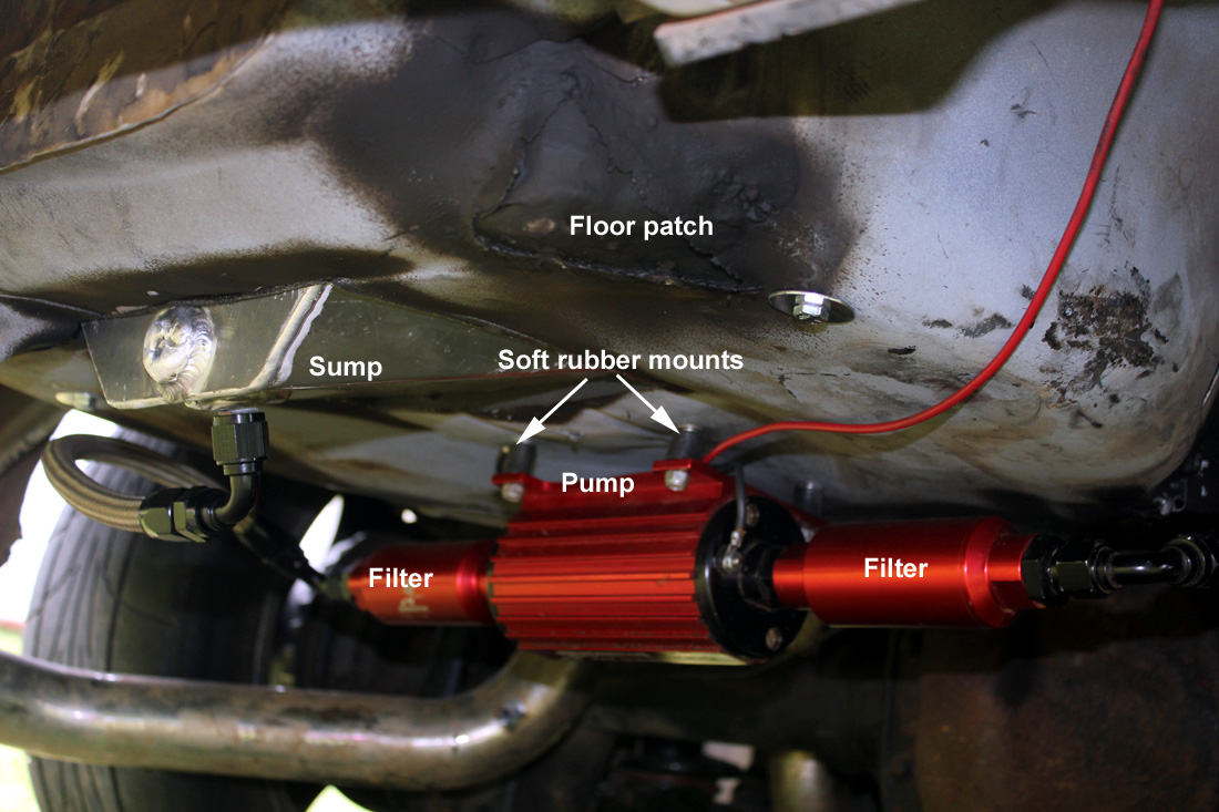
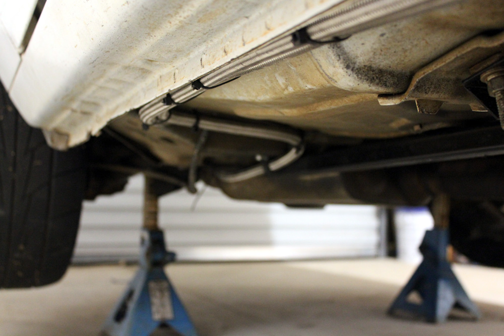
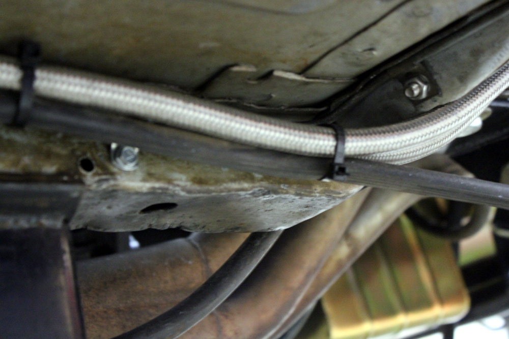
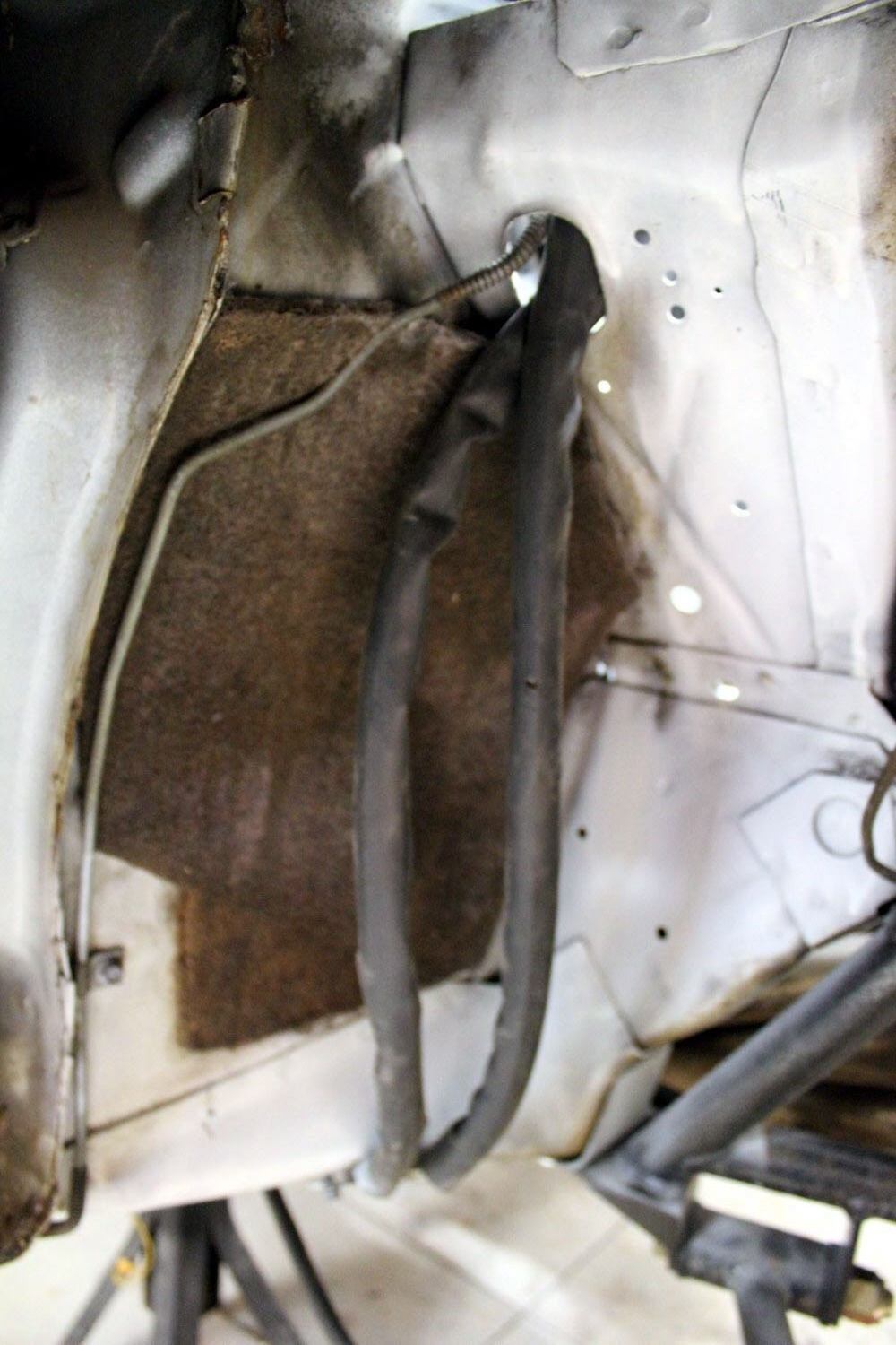
details: I'm using the stock tank with the UPR pickup, A1000 pump, 8 an braided to engine, 6 an return. Car has an 0n3 turbo, so exhaust only on passenger side near engine (then a y pipe and dual exhuast) - thinking I might run fuel under drivers side to keep it farther away from exhaust?
 
#2 · (Edited)
route them whatever way makes the most sense to you.....
everybody's setup is slightly different


I went from sump to pump...to the passenger side and up to the front...


Sump to pump


down the passenger side


up thru the wheel well behind the strut tower into the engine bay


Inside the engine bay....
in to the rear of each rail
out the front with a 180* fitting...and lines go over to the fuel regulator mounted to the strut tower....


return lines follow the route back the same line as the main feed came up....side by side.


also, since you mentioned going drivers side to stay away from the exhaust..in reference to where it lies in relation to my exhaust.....


  • Like
Reactions: massacre
#21 ·
route them whatever way makes the most sense to you.....
everybody's setup is slightly different


I went from sump to pump...to the passenger side and up to the front...


Sump to pump


down the passenger side


up thru the wheel well behind the strut tower into the engine bay


Inside the engine bay....
in to the rear of each rail
out the front with a 180* fitting...and lines go over to the fuel regulator mounted to the strut tower....


return lines follow the route back the same line as the main feed came up....side by side.


also, since you mentioned going drivers side to stay away from the exhaust..in reference to where it lies in relation to my exhaust.....


Which headers are those? If you remember?
 
#4 ·
also, for reference....
mine is a dual 10 to single 12 out of the sump into the pump
then a 10 out of the pump all the way to the front of the car where it hits a Y to branch off to the rear of the fuel rails with an 8an
then the return is 8an the whole way back.
 
#5 ·
I wouldn't route fuel lines into a wheel-well where debris kicked up by the tire could strike them. If you keep the lines in the same general area where the factory routed them chances are you'll be in areas that are generally safe for the lines. You want to use rubber lined clamps so secure the lines and allow a bit of safe movement. If you have to route in areas close enough to the exhaust system to concern you, just build a bit of heat shield - aluminum gutter flashing is cheap and easy to fabricate (you can use scissors to cut it).

I ran aluminum hard lines on mine - not exactly like the bottom of the fox, but very similar. I ran the return line in the stock location under the driver's side inside the frame rail. It parallels the brake lines and the fuel tank vent line. I ran the supply line in the same location on the passenger side. The return line crosses over to the passenger side parallel with the front cross member -- where both lines connect to the stock Mustang hard lines down under the alternator.

Pics below --- use rubber and wiring loom to insulate the lines so they don't touch metal anywhere between the tank and the connection the fuel rails -- don't want any abrasion to cause a problem down the road.


Here's an example of a gutter-flashing heat shield - the hard line passes behind it and is shielded from the converter heat. I used existing threaded holes in the frame rail to bolt it in place.

 
#6 ·
There's no danger running things up thru the wheel well....
Its in the cavity behind the liner...not exposed at all
The lines under the car are more exposed than the ones in the wheel well...
And a rock isn't going to be enough to hurt the line....
going over a speed bump and hitting it because you are too low has more chance to damage lines on the underside than any thing else does..
 
  • Like
Reactions: massacre
#7 ·
going over a speed bump and hitting it because you are too low has more chance to damage lines on the underside than any thing else does..
Given that things like the frame rails (front and rear), the bottom seam of the rockers, the center section of the rear end, the cross member, the oil pan, the bottom of the bell housing, the front control arms and the bottom of the transmission would have to be ground completely off BEFORE you get to the fuel lines and brake lines -- I don't think there's much to worry about. As I said before - if you follow the factory fuel line/brake line routing -- you're going to be about as safe as you can be.

I chose my words carefully Scott - I simply said I wouldn't route them in the wheel wells and stated the reason why. You get to do what you think is right. And the OP gets to decide what they want to do.
 
#12 ·
I'm digging out this old thread because in researching this topic, no one seems to have pictures of the area where the mufflers go... I'm trying to figure out where to run 2 -8an stainless hoses going from where I go over the rear axle to get it outside the sub frame connector. I have Flowmaster 2 chamber mufflers with dumps. The muffler pretty much takes the space where many people route their hoses... any suggestions? Pictures?

Thanks,
Greg
 
#14 ·
Fuel system is out of car at this time. I ran two #16 sump to two 500gph pumps, two #10 pump to front. Mine is a back half car with full cage. 2x3 square channel where most cars have sub frame conectors. One #10 to a front cell that is then # 10 to a mechanical pump that has a post carbs regulated. The other # 10 direct to a 4 port that feeds the N20 sytems. A #10 return front to rear, both electric pumps have #8 bypass direct to sump. I also ran mine up under the front fender and into the engine compartment through the fender liner. New combination probably going with fender exit headers so the fuel will just come up inside frame rail up under fire wall.
 
#15 ·
I just reworked mine for 120 lb injectors. I ditched my Aeromotive pump for a Holley, and then after installing the pump I ran pressure tests. I only have pressure <1 psi drop using a number 8 feed to the front. My return line barely keeps up, but has enough head room.

I was going to change all the lines but looking at pressure, the #8 feed was fine. Calculators on line also show it was adequate, like this calculator. Follow through these steps:

Pressure Drop
 
#18 ·
That's a good point, but pressure caused by gravity is independent of the liquid's column diameter. It only has to do with the liquid's specific weight (gamma) and "height" and g force.

Take 0.3 times the bee-line distance times the g-force and that is the psi for gasoline. 10 feet and 3 g's is .3*10*3 = 9 psi head.

0.3 works for gasoline. Alcohol is about 0.35 Water would be about .44.

Doing water, a column 100 feet length working against 1 g would have .44*100= 44 psi. If I wanted to feed customers water at 44 psi I would put a water tank or a huge water reservoir 100 feet above their faucet height. Look around the flat lands, and most water tanks that do not use external regulation are just over 100 ft tall. It requires 44+ psi to fill them through a one inch pipe, or a 5 foot pipe.

If houses used 80-90 psi, gravity regulated pressure water tanks would be 200ft above the faucet height, regardless of tank or pipe diameter.

Since pumps and fans are much more sensitive to inlet pressure than outlet pressure, the pump should be back by the tank. Inlet pressure loss from negative head caused by acceleration could kill a pump's capacity.
 
#19 ·
My biggest issue is coming around the turn near the front fender area. Im only running a single -10 Feed line, and running it into the engine bay in a very clean manner is a pain, I have a shaved engine bay and I want a finished product that is nice.

On that note, what I done was use bulk head fittings, much like what can be used on a fuel cell itself. I drilled a single hole into my engine bay, installed the fitting, then I have a -10 fitting on both sides of the engine bay. Im thinking about installing a couple of the fuel line valves as well so maintenance would be easy down the road, if I ever need to shut off the fuel with a full tank.

Along the frame rails of the car, I tucked it up behind the full length sub frame connectors, if the car does bottom out, it will bang the connectors well before a fuel line. I have a small gap exposed on mine on the transition at the fender, its about 3/4" if a gap, I will probably fabricate some kind of shield for it for added insurance. Its right where the fender liner ends.
 
#24 ·
I’m about to route a new feed line for my supercharged setup in -8 PTFE hose. Will post pictures, for sure. My power levels aren’t that high, though… support for roughly 750 hp is enough, so using -8 for the feed, upgraded rails, regulator and stock feed line converted into the return.